There are many different measurements to indicate how loud a signal is on our mixers, recorders or within our DAW software. This article tries to explain the basics so you know where to expand your knowledge, what some important reference values are and maybe even how to built your circuits in order to acommodate the expected voltages.
Different scales
A lot of the confusion stems from the fact that we have a metric ton of different units some of which indicate the level of our audio signal in the digital domain (e.g. in the DAW, on our field recorders level meter), while other units specify some value from the analog domain. To our horror we notice, that it might be even unclear which physical quantity is measured – an example:
- $dB_V$ and $dB_U$ for electrical voltage level (e.g. in Volts)
- $dB_m$ and $dB_W$ for electrical power level (e.g. in Watts)
- $dB_A$ and $dB_{SPL}$ for sound pressure level (e.g. in Pascal)
- $dB_{FS}$ for digital levels (relative to “Full Scale”)
- and many more…
For our purposes we want to focus on $dB_U$ for voltages and $dB_{FS}$ for digital levels. Depending on the field we are in the other units might be used (e.g. when you buy speakers and want to know how loud they are). The important takeaway here is: there is more than one dB scale.
What does dB mean?
The short form of dB stands for Decibels and as such describes the relation between two values. That means to make sense of any value that you get on a dB scale you need to know the value the scale is referenced to.
This is probably the easiest to understand when we look at the digital $dB_{FS}$ scale: When we look at digital audio we get a limited range within which we can represent our values. Think about digital pictures where we can overexpose parts of the pictures in such a way that their value clips and is either stored as the whitest white – any information beyond that is lost. You can’t just darken the picture afterwards and get back the parts that you overexposed, you will just get a solid block of a single color in the overexposed areas. Similar to this there is a limit to the level digital audio can have, because there is a limited number of values to encode it. The number of possible values we can get depend on the bitdepth of the device: with 8 Bits we get $2^8 = 256$ distinct values, with 16 Bit we get $2^{16} = 65\space 536$ possible values, for 24 Bits we get $2^{24} = 16\space 777\space 216$ steps and for 32 Bit we get $ 2^{32} = 4\space 294\space 967\space 296$ values. Because a audio signal swings both in the positive and the negative direction our assumed zero point is right in the middle of the range and if the value from our ADC (Analog-to-Digital-Converter) exceeds that number, it is “overexposed” or clipped – this would be the maximum possible digital level.
The $dB_{FS}$ scale is referenced to this maximum possible digital level. This means anything above $0 \space dB_{FS}$ gets clipped away – $0 \space dB_{FS}$ is the absolute maximum level our digital audio can have. Any audio that we would realistically work with is therefore in the negative range, e.g. the EBU (European Broadcast Union) agreed on a maximum level that anybody should use for radio and broadcast of $-9 \space dB_{FS}$. For cinema $-9 \space dB_{FS}$ is the dialogue level (although there is no official norm that I know of) with a maximum of $-6 \space dB_{FS}$.
Importantly however there is no real indication how loud a sound with a digital level $0 \space dB_{FS}$ actually is. This is totally understandable: I could turn my speakers all the way up, mix my piece of music, export it, send it to you and you have your speakers turned all the way down and can barly hear anything. This is why you can calibrate your sound system to different studio reference levels (this is usually done with pink noise and a SPL-meter that gives you a value for how loud the sound is that comes out of your speakers). We can also look at this in terms of recording: Our goal for recording is to fit our incoming signal (e.g. coming from a microphone plugged into a microphone preamplifier) into the range of possible values – the less bits we use the more accurately we must do this. However, there is no indication how loud the actual sound waves were that excited the membrane of the microphone. This is something we can’t see just by looking at the numbers afterwards, unless someone noted down the Gain value of the preamp and they did a calibration of the microphone to figure out which sound pressure produces which voltage.
When we look at the actual voltages that come out of your sound card different dB scales are used. As listed above voltages are typically measured in $dB_U$ and $dB_V$. They are basically the same thing but differ in the reference voltage $V_0$. The $dB_U$-scale is used in Europe, while the $dB_V$-scale is mostly used in the US. A value of $0\space dB_U$ is referenced to a $V_0$ of $0.7746 \space V_{RMS}$, while a value of $0\space dB_V$ is referenced to $V_0 = 1\space V_{RMS}$.
A logarithmic scale
Because our hearing perceives loudness in a logarithmic way all dB scales are logarithmic as well – this makes it quite intuitive to work with dB values (as opposed to raw datatypes like integers or floats or analog voltages). What does this mean? It means when we change a voltage by $+6\space dB_U$ the output voltage level is doubled.
Humans usually have a hard time understanding exponential functions (which we can wittness on a grand scale when looking at both capitalism and the climate catastrophe) – changing our scale to a logarithmic representation lets us reason about exponential changes on a linear scale.
Aside: Other scales
All mentioned measurements just look at a single Sample, so a single point in time – a typical audio setup would have a minimum of 44100 of these per second. To see a clipping audio at that rate would be impossible even with superhuman eyes, because our computer monitors are far too slow for this. This means all actual metering systems we look at somehow average or integrate samples over time. The details of this are out of scope for this article, but have a look at PPM, VU or K-20 scales to get a feeling for the differences.
Conversion between $dB_U$ and $V_{RMS}$
If we want to interface audio gear with each other we need to make sure both devices have compatible voltage levels. E.g. a microphone usually has a voltage level of $-60$ to $-40 \space dB_U$ this is much, much lower than e.g. the output level of a modular synthesizer at roughly $+19 \space dB_U$. So to get up to modular levels we would need at least $+50 \space dB_U$ of amplification.
The following formula let’s us convert these $dB_U$ values to voltages:
$$L = 20 \cdot \log(\frac{V}{V_0}) \hspace{30mm} V=V_0 \cdot 10^{\frac{L}{20}}$$
- $L$ … Level in dB (which dB scale depends on the used value of $V_0$, see below)
- $V$ … Voltage in $V_{RMS}$
- $V_0$ … Reference Voltage in $V_{RMS}$ ($0.7746 \space V_{RMS}$ for $dB_U$, U$1 \space V_{RMS}$ for $dB_V$)
Conversion $V_{RMS}$ to $V_{pp}$
The RMS voltage is the effective voltage of an AC signal. This is what is typically used to specify AC voltages (e.g. 230 V AC from the electrical grid are actually the RMS-value). The peak-to-peak voltage $V_{pp}$ is actually higher and specifies the voltage from the highest peak to the lowest “valley” of the signal).
These are the formulae to convert from one to the other:
$$V_{pp} = 2 \cdot \sqrt{2} \cdot V_{RMS} \hspace{20mm} V_{RMS} = \frac{V_{pp}}{2 \cdot \sqrt{2}}$$
Typical levels
| Level | Level L in dB | Voltage RMS | Voltage peak-to-peak |
|---|---|---|---|
| Eurorack Modular Synth (Maximum Level) | $+21\space dB_U$ | $8.485\space V_{RMS}$ | $24 \space V_{pp}$ |
| Eurorack Modular Synth (Modulation Level) | $+19\space dB_U$ | $7.07\space V_{RMS}$ | $20 \space V_{pp}$ |
| Eurorack Modular Synth (Audio Level) | $+13\space dB_U$ | $3.54\space V_{RMS}$ | $10 \space V_{pp}$ |
| European studio level - EBU broadcast level | $+6\space dB_U$ | $1.55\space V_{RMS}$ | $4.38 \space V_{pp}$ |
| International studio level - USA | $+4\space dB_U$ | $1.228\space V_{RMS}$ | $3.47 \space V_{pp}$ |
| Domestic recording (Smartphones, Laptops, …) | $−10\space dB_V$ / $−7.78\space dB_U$ | $0.3162\space V_{RMS}$ | $0.894 \space V_{pp}$ |
| Microphone | $-60$ to $-50 \space dB_U$ | $0.0008$ to $0.002 \space V_{RMS}$ | $0.002$ to $0.007 \space V_{pp}$ |
Example 1: Gain Calculation
Let’s say we want to amplify the signal from a laptop ($0.3162 \space V_{RMS}$) loud enough to be used in a modular synthesizer ( $3.54 \space V_{RMS}$). How much Voltage Gain would we need?
We could first calculate the Gain without unit:
$$Gain = \frac{V_{out}}{V_{in}} \hspace{30mm} Gain = \frac{3.54\space V_{RMS}}{0.3162\space V_{RMS}} = \underline{11.2} $$
To get a value in $dB_U$ we could do the following:
$$Gain_{db_U} = 20 \cdot \log{(Gain)} \hspace{8mm} Gain_{db_U} = 20 \cdot \log{(11.2)} = \underline{+21\space dB_U}$$
So to get our laptops line signal up to modular levels we would need a Gain of at least $11.2$ or $+21\space dB_U$. We could directly put this into our opamp formula and calculate the needed resistance values.
If we want to go the other way (from eurorack to laptop) we just need to swap $V_{out}$ and $V_{in}$ and we will naturally get a gain of $0.089$ or $-21 \space dB_U$. Here we can immidiately see one of the advantages of working with dB values over gain values – both amplification and attenuation will give us the same values.
Example 2: Attenuator calculation
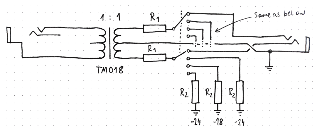
This is a small circuit that galvanically isolates two audio sources/sinks
Note:
- We have an unbalanced connector on the left going into the TM018 1:1 transformer (ignoring the center tab of the transformer)
- We have an balanced connector on the right that essentially takes the center tab of the transformer as ground, and the outside tabs as left and right signals.
- We have a rotatry switch which either does nothing or adds a resistor $R_2$ to ground which froms a voltage divider with $R_1$ (upper half of the circuit not drawn)
- Because the left side uses the outside tabs of the transformer and the right side uses the center tab and the outside tabs our signal wil be attenuated by a ratio of $1:2$ or a factor of $0.5$.
We can just set any fixed value for $R_1$ (I chose $10\space k \Omega$), but how do we calculate the values for the resistor $R_2$ that we select with our rotary switch?
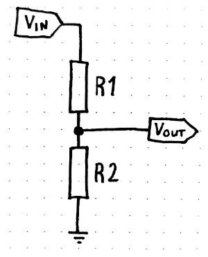
Let us start with what we know. We know we have a voltage divider and we know what kind of attenuation we want to have (24 dB, 18 db, 12 db, 6 db). As a short reminder this is what a voltage divider looks like:
The keen reader might realise there is a third thing we already know: $V_{in}$. We don’t know it in the sense that we know what kind of voltage will be there in the end, but we already know that it is going to be half of the voltage that we have on the unbalanced connector. So let’s just say this is 0.5 V. Let’s plug this into the gain formula to figure out the gain of our transformer:
$$Gain = \frac{V_{out}}{V_{in}}$$
Our transformer has an input of 1V and an output of 0.5V which gives us a gain of 0.5.
Next we need to figure out what gain our unloaded voltage dividers should have. Let’s start with the setting where we wanted an attenuation $L=-24\space dB$. For this we can use the following formula:
$$V_{out} = 10^{\frac{L}{20}} \hspace{5mm} = \hspace{5mm} 10^{\frac{-24}{20}} = \underline{0.0630957\space V}$$
We can now plug this into the gain formula using our hypothetical input voltage of 0.5 V:
$$Gain = \frac{V_{out}}{V_{in}} \hspace{5mm} = \hspace{5mm} \frac{0.0630957\space V}{0.5\space V} = \underline{0.1262}$$
Now we know our voltage divider needs a gain of $\underline{0.1262}$ to give us 24 dB attenuation – but how do we now get to the value of $R_2$?
Having a look at the formula for the (unloaded) resistive voltage divider could be useful:
$$V_{out} = V_{in} \cdot \frac{R_2}{R_1 + R_2}$$
As you might have noticed we can replace $V_{out}$ and $V_{in}$ with the Gain variable from above
$$Gain = \frac{R_2}{R_1 + R_2}$$
and solve for $R_2$
$$R_2 = \frac{-Gain \cdot R_1}{Gain - 1}$$
Now we can insert the values. We assumed $R_1 = 10\space k\Omega$ and we know our targeted Gain, so we have all we need:
$$R_2 = \frac{-0.1262 \cdot 10000\Omega}{0.1262 - 1} = \underline{1444.26\space \Omega}$$
So to attenuate by 24 dB $R_2$ needs to have a value of $1.4\space k\Omega$.
A lot of math. I condensed this down into Python code here:
import math

# Upper resistor of voltage divider
r1 = 10000

# Input voltage, this is behind a 1:2 transformer so vin is 0.5
# if there is no attenuation use a value of 1.0
vin = 0.5

# Gain steps to calculate
steps = [-6, -12, -18, -24]


def db_to_gain(db, vin):
  """
  Convert a db value to gain (given a certain vin)
  """
  vrms = 10**(db/20)
  return vrms/vin

def get_r2(gain, r1):
  """
  Calculate the value of the second resistor R2 in the voltage divider
  """
  r2 = (-gain * r1) / (gain - 1)
  return r2


# Print some headers
print(f"Vin = {vin}")
print(f"R1  = {r1}")
print("\ndBu    Gain   Gain (total)     R2")
print("-"*40)

# Calculate all the resistor values and print the tables for each step
for db in steps:
  gain = db_to_gain(db, vin)
  r2 = get_r2(gain, r1)/1000

  # Negative resistance is not allowed
  if r2 <= 0:
    r2 = 0.0
  print(f"{db:3}: {gain:6.2f} {gain*vin:6.2f} {r2:16.2f}k")
Vin = 0.5
R1  = 10000

dBu    Gain   Gain (total)     R2
----------------------------------------
 -6:   1.00   0.50             0.00k
-12:   0.50   0.25            10.10k
-18:   0.25   0.13             3.37k
-24:   0.13   0.06             1.44k